"Guff" Solid State Tesla Coil!
Updated 2/4/2026
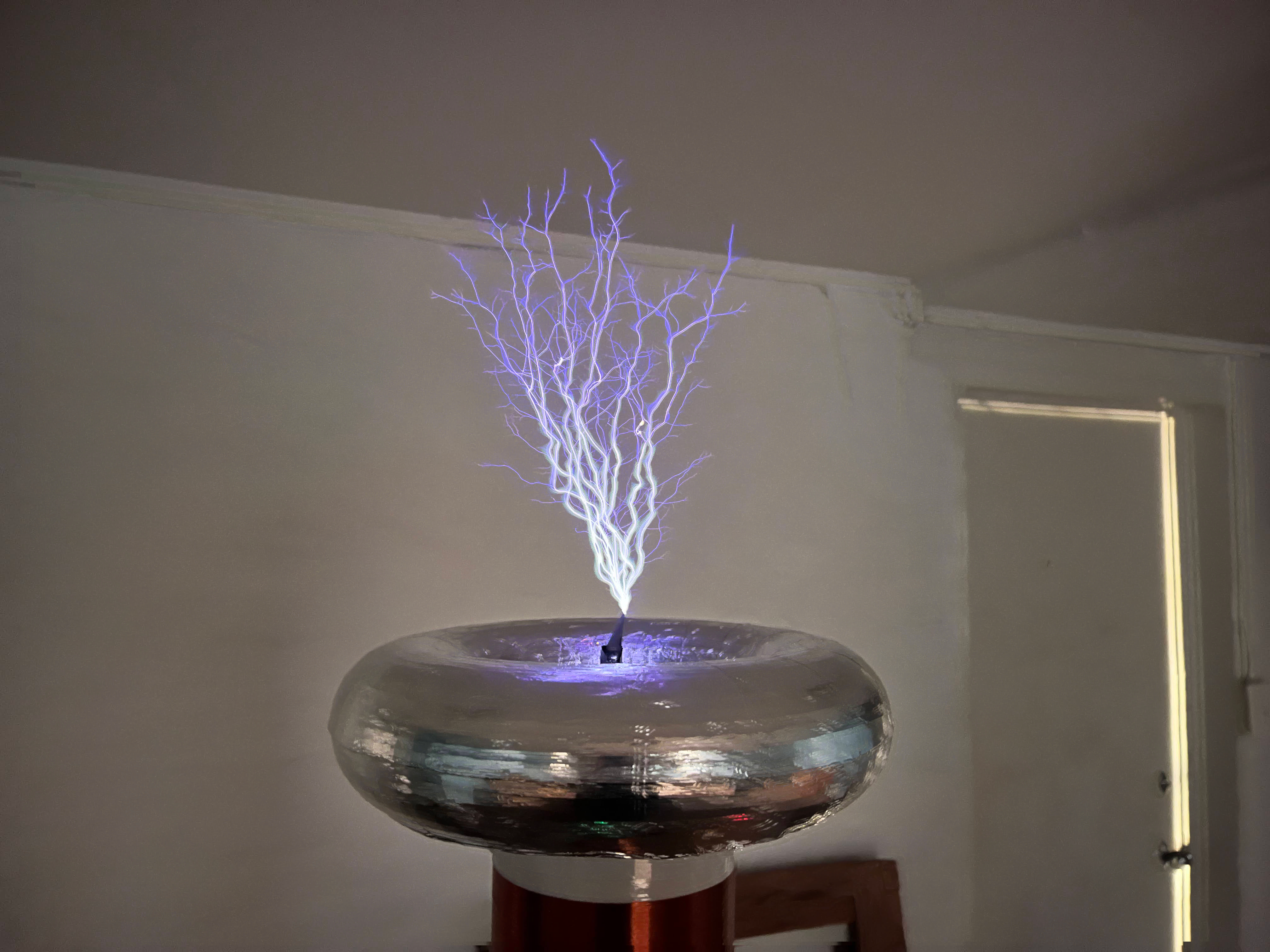
My new tesla coil is an ~500W, half bridge IGBT driven, interrupted, 2.5ft tall coil! My construction has improved a bit with
this nice computer power supply case that I gutted for my electronics which serves as a faraday cage for my low
voltage circuitry!
This page is pretty technical, and all about the circuit! See also SSTC
or Slayer Exciters for more interesting beginner information!
The coil was built with a couple optional modes of operation: staccatto operation to create longer and straighter
arcs, and dual resonant operation to raise power input in the primary coil to kilowatts. Currently, these
two modes of operation are still WIP. This coil runs off antenna feedback and the half bridge is driven by DC power
interrupted by square pulses. It achieves almost 30cm long arcs at full power levels!
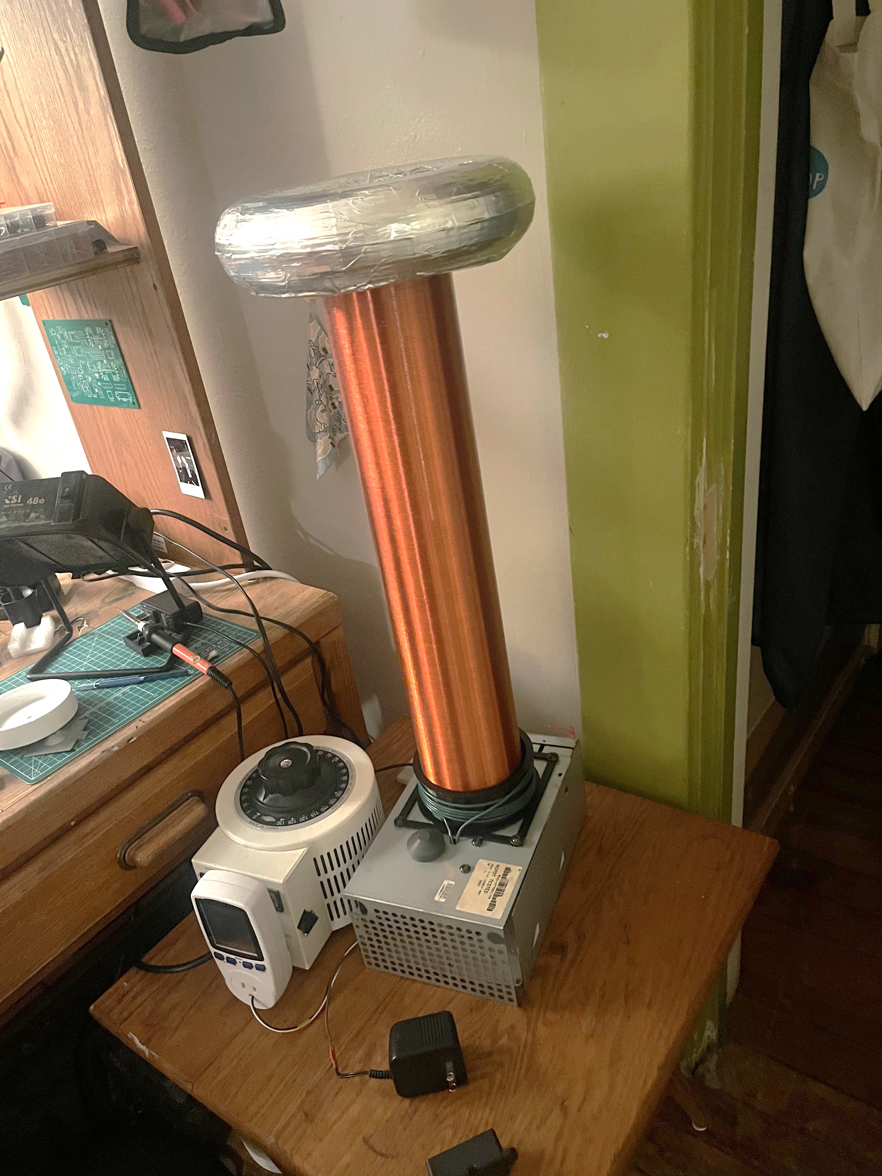
On the right is a long video of my first test of the coil, it's using a tiny cap as a topload, limiting its arc length
by increasing the resonant frequency of the secondary. The rolling shutter of my camera occasionally prevents
the arc from being seen.
The construction of this tesla coil was during my time at the Michigan Cooperative House "Luther", hence the
name "Guff tesla coil" which comes from the commune term meaning: "General Unrestricted
Free Food" but extends past just food to all community items / goods. I made
this for the annual Halloween party!
I've occasionally had the issue that high power being drained into the earth ground of the wall outlet
have created a standing voltage on the ground of the entire circuit in the room. This causes arcs to start
coming out of things like USB-C cords and generally frying electronics on the same circuit. Because of this
undesired effect, I'm doing all of this experimentation in a spare room in the basement of the commune.
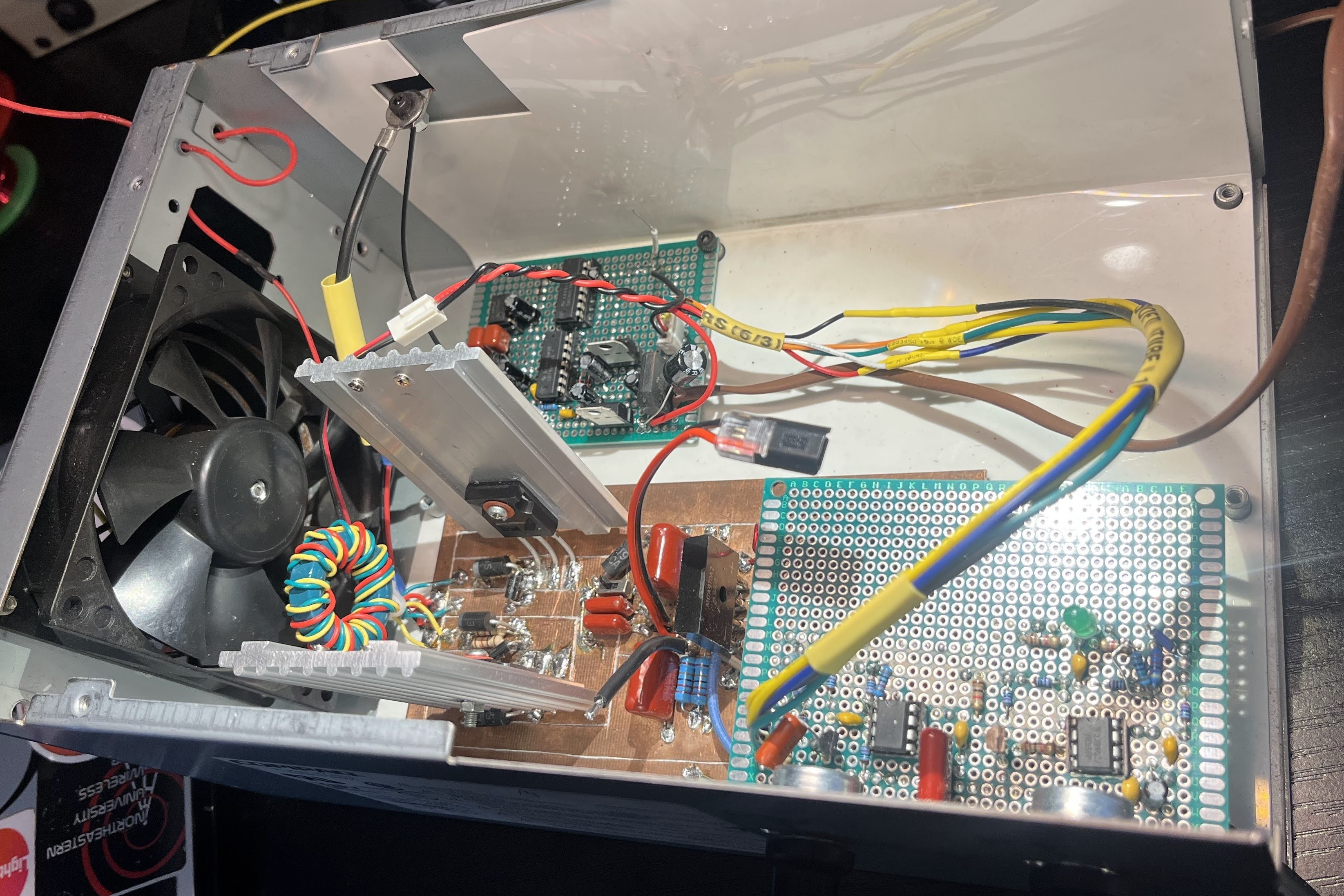
Here is the inside of my driver box. You can see the "Manhattan" high power circuit for
my high power half-bridge driver. I prototyped the circuit on copper clad for power, and to avoid inductive
traces. I use the "Leo's Bag of Tricks"
circuit carving technique, I've made a couple of these custom x-acto carvers as well.
The board mounted higher up contains the two potentiometers which adjust the interrupter for
the circuit. The dense, green board in the corner contains the IGBT gate drivers, power regulators, and flip-flop
circuitry needed for dual resonance mode.
Some elements of this circuit get HOT! I've kept the power supply fan in the box!
All about: The Half Bridge
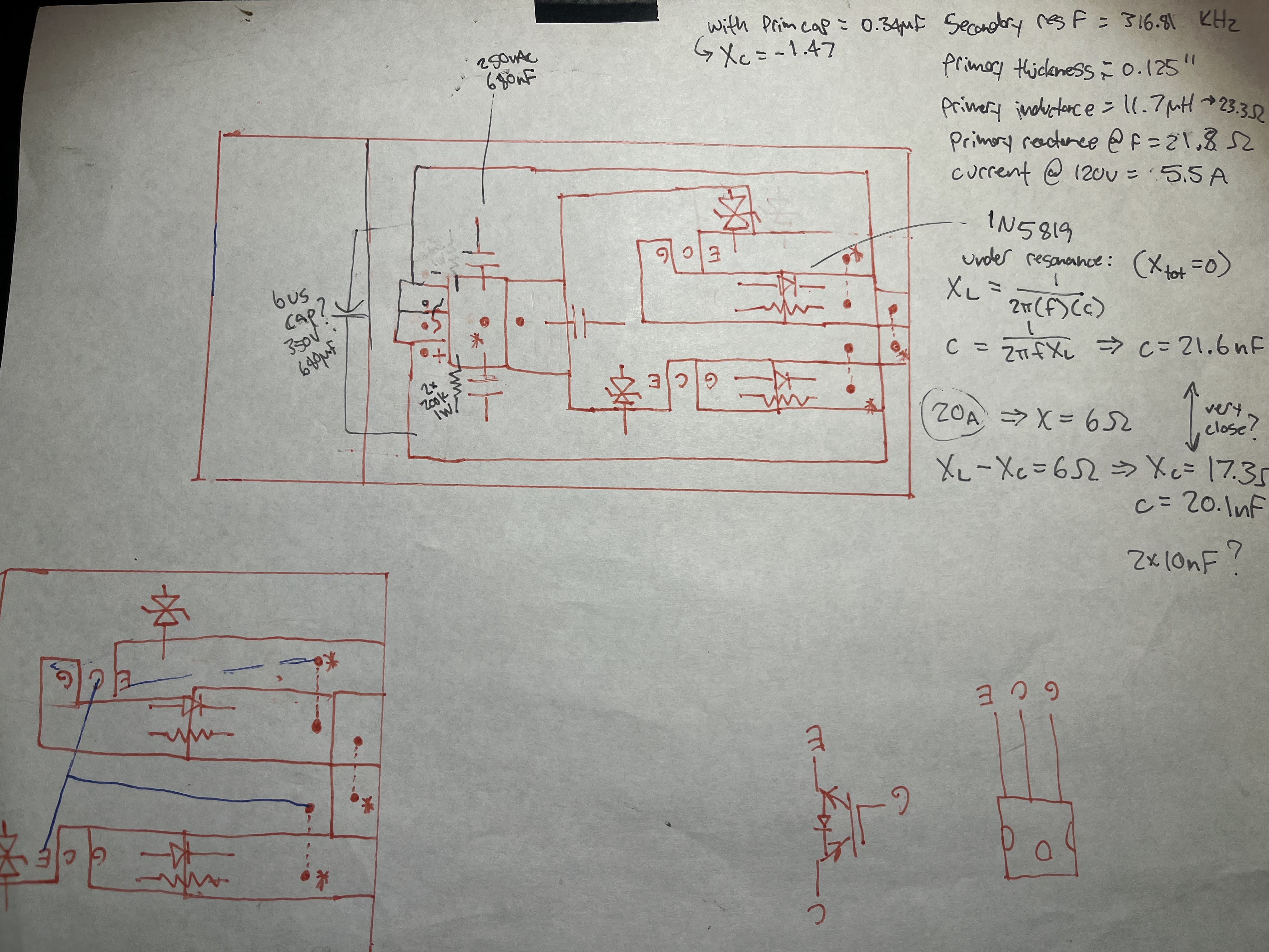
Here is my plan on paper for how to construct the half bridge to drive my primary coil! Of
course this is based on my circuit design first. The schematic capture for the actual circuit
is below.
This paper does have a little bit of the math for expected currents through the circuit and primary capacitor value for dual-resonance
mode!
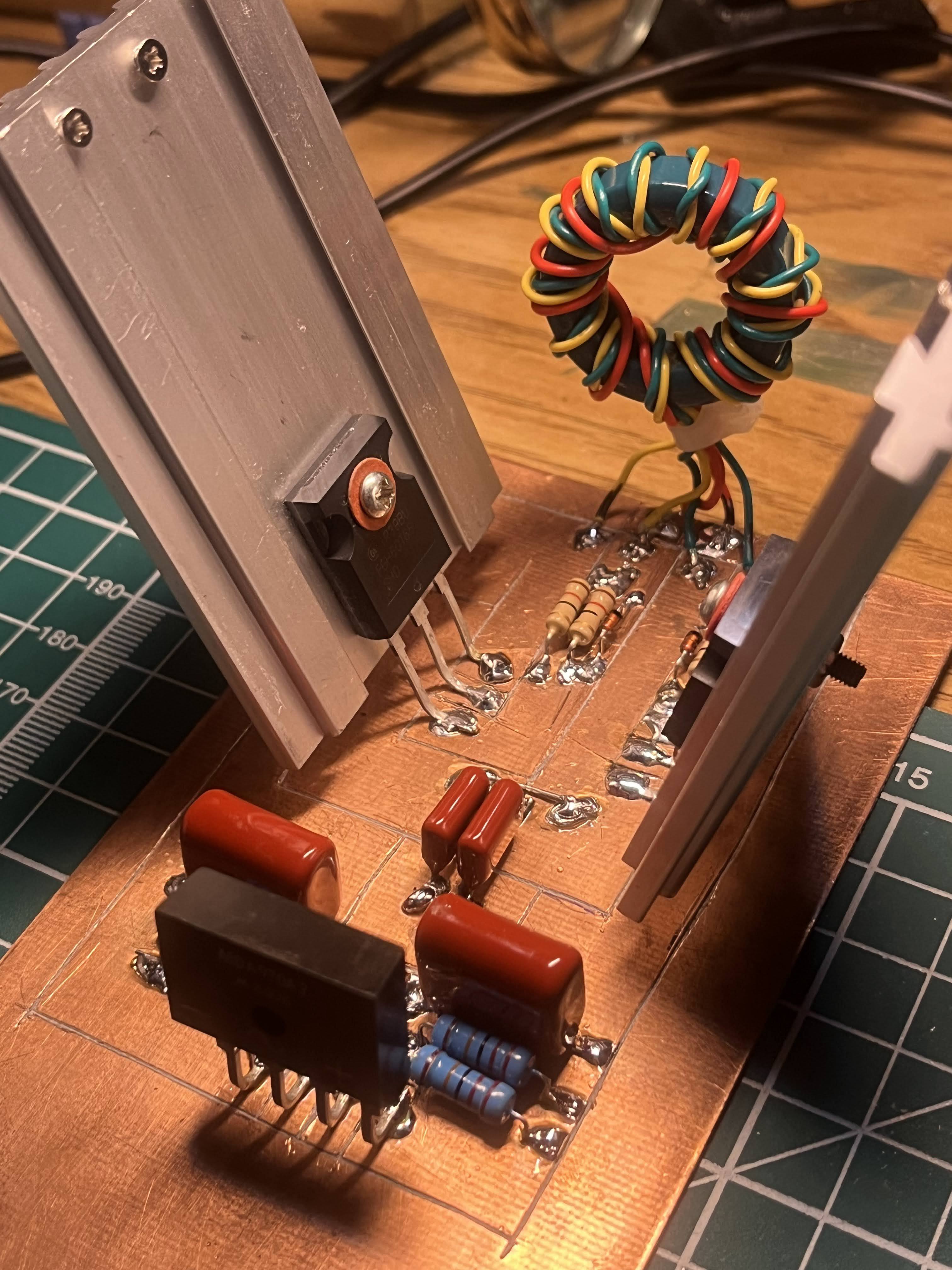
This is my constructed half-bridge driver! The heat sinks are actually aluminum pieces from the frame of a whiteboard which I cut up and drilled into. I found them to be a fine size as my IGBTs don't actually get hot in this circuit! Maybe it's good design?? Luck?
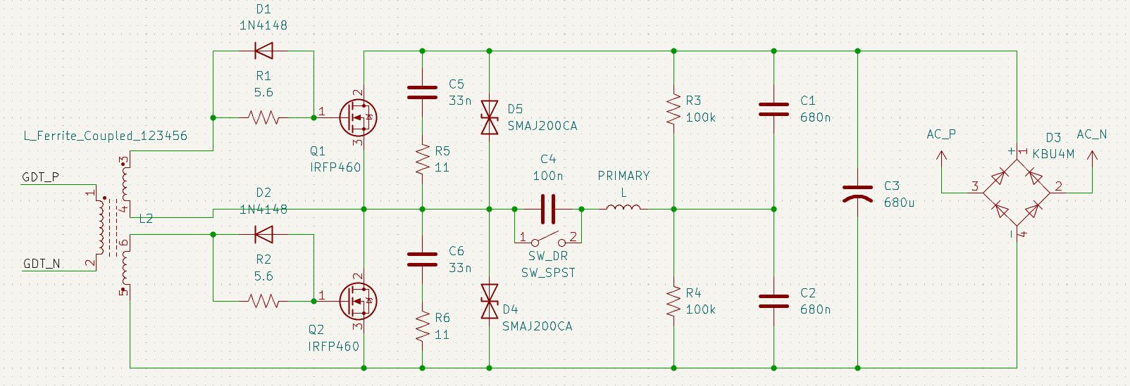
This is the schematic capture for the completed half-bridge driver. These IRFP460 IGBTs are rated for upwards
of 500V at 20A, so I shouldn't stress them too much during the operation of this coil (theoretically).
Notice that both gates are driven through a gate drive transformer (GDT). The GDT (along with gate resistor and diode)
ensures perfect inversion of the two IGBT's on-states, stepped gate drive voltage for Vt, and electrical isolation from
the low voltage electronics.
In my attempt to protect the IGBTs from voltage spikes from flyback in the primary, I've added 200V TVS diodes
across the Collector-Emitter, as well as an RC snubber calculated to prevent an ~4.25MHz ringing during
operation.
The idea of the switch across the capacitors in the center is to enable or disable so-called "dual resonant"
mode, where opening the switch to add the capacitor would allow the primary and capacitor to become its own
resonant circuit, allowing for higher power.
All about: Gate Driving Circuit
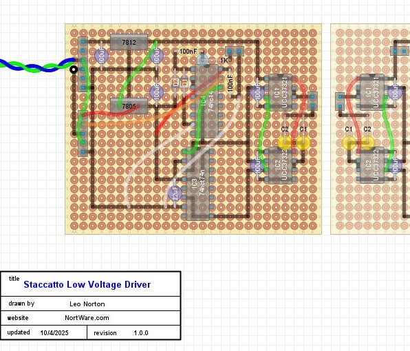
I designed the layout of these boards in "DIY Layout creator". It's a very simple but sweet software which allows you to layout prototype boards, then flip them to see the top and bottom side wiring.
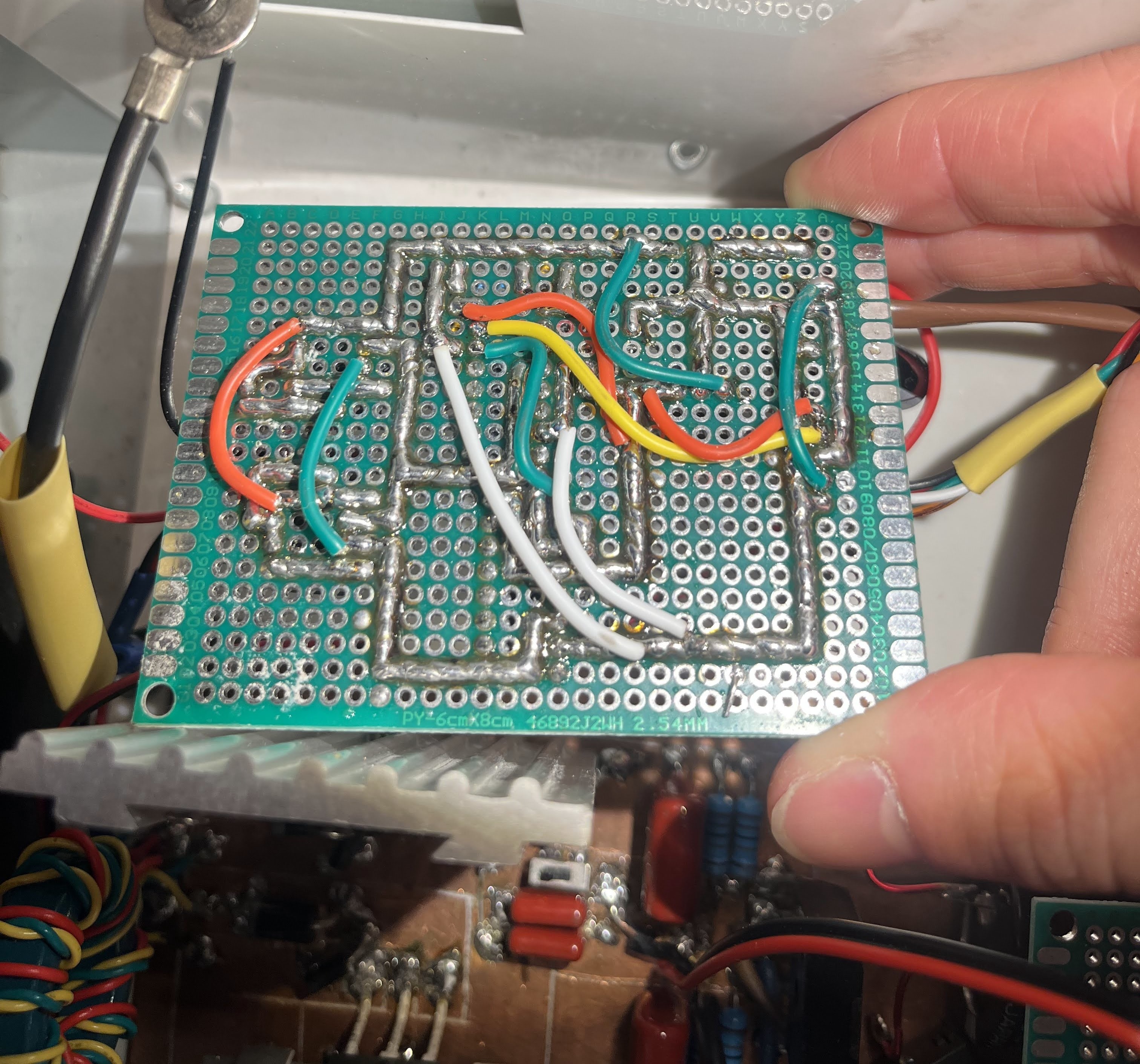
This is not great engineering practice, but I find it extremely meditative to prototype my boards using the "giant solder blob" technique. My last (less advanced) coil used a proper PCB, but I wanted to whip this one up in a matter of a couple weeks. I have found this reliable enough as far as prototyping techniques go.
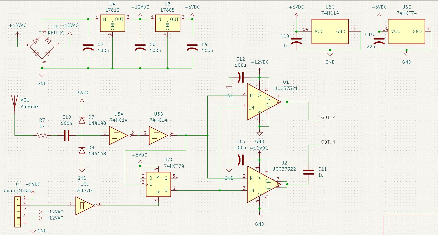
This is the schematic capture for the gate driver board! This board has a few functions. It rectifies
and regulates power for all the low voltage circuitry. It receives a high Vpp amplitude sine signal
from the antenna and uses diode clamping and a schmitt buffer to convert it to digital, where it can be
processed as an input to digital chips. The interrupter is inputted and powered through "J1", and the two
UCC3732X ICs drive the gate drive transformer (GDT).
The flip-flop or 74HCT74 ic is always synchronizing the inverter to the interrupter. This prevents
the interrupter from switching off the inverter right in the middle of a particularly large current draw, possibly
killing the IGBTs. This feature is only needed when operating in dual resonant driving mode.
The antenna is just a piece of wire (of any length) that exits the faraday cage (metal box) which the
circuits are otherwise contained in. Just from EMI, a voltage much greater than 5v is produces, allowing the
interrupter to be driven based off feedback from the tesla coil.
Finally, the gate drive ICs are dedicated inverting(37322) and noninverting(37321) types, and drive current
into the GDT on the half bridge board!
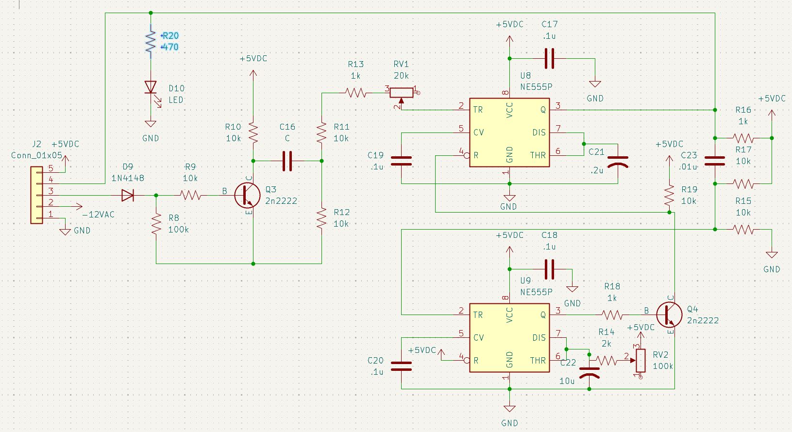
All about: The Interrupter
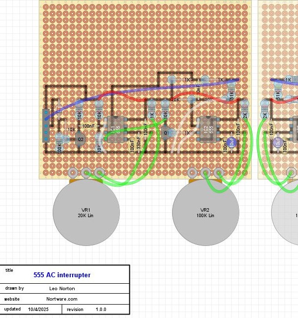
Here's my DIY layout creator design for this board, it consists of two potentiometers which interface this dual 555-timer circuit to create an interrupter pulse output for the gate driver board. The two potentiometers are accessible from the outside of the faraday cage, and allow tuning of both the pulse frequency of the interrupter and thus electrical arcs, and the pulse width of the arcs, or how long the coil is running continuously (on the order of 1u to 1m second).
Testing the signal driven by this interrupter shows that it's doing its job, and varying pulse length well, but something is off in my circuit keeping this "sine" envelope from being a uniform square wave across it. I remedied this later with a large bus capacitor, shaping this into a pulse rather than a sine.
The interrupter has two functions, the first is fairly easy, it needs to create a digital pulse of an equal pulse duration
but variable frequency, and, for my added "staccatto" functionality, it needs to sync the start of the pulse to
the first quarter of the mains AC waveform.
The idea of syncing the pulse to mains voltage is that when the power through the half bridge is increasing during
the first quarter of the mains sine wave, the tesla coil output is enabled. This is as inputting a pseudo-ramp
to the power bus of the half bridge, rather than a simple DC or AC voltage. In this mode of operation, the arcs
outputted from the tesla coil are much longer and straighter in contrast to the shorter and more branching arcs
of a square output.
This board connects to and is powered from the gate drive board. The 12V ac signal from a 12V transformer is
inputted into this board and its zero crossing is detected with the first transistor. This pulse from zero crossing
the mains AC triggers the first 555 timer, which is set up as a monostable multi-vibrator and times the pulse width.
The second 555 timer pulls the first timer's reset pin down during a "cooldown" period set by the second potentiometer.
In this way, the effective frequency output of the interrupter can be set.
Wow you got to the end! Thanks for reading one of my most technical pages! Learn about interesting other coils here!