My New Quasi-Continuous-Waveform Coil!
Updated 5/25/2025
I am currently working on a brand-new tesla coil circuit and setup which uses the so called
quasi-continuous-waveform (QCW) topology. This tesla coil is one of my most advanced TC circuits so far,
built off an electrically isolated driver circuit which uses analog components and ASICs to generate
high power signal pulses with precise timing and frequency. The mains-power AC signal is used
as a signal generator to start an arc just as power increases!
These are some videos of the coil in action! Check out the arc lengths and its ability to easily light
a large compact-florescent bulb! To the left is a video of my first full power test with the coil, I'm still working
on getting much more arc-length out of this design!
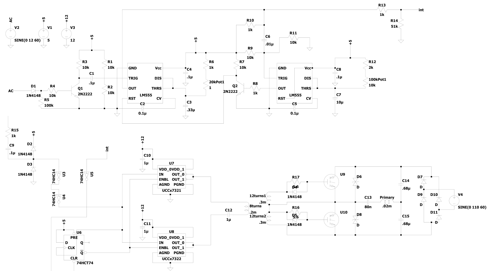
The schematic above represents the medium-frequency driver for my new tesla coil's printed circuit board. The
only aspect not represented above is the power supply circuits on the board. Much of the topology is similar
to other solid state tesla coils. I opted for a no-microcontroller approach with a PWM signal being generated
by 555, schmitt-trigger, and flip-flop ASICs. This is very close to the topology popularized by Lone Oceans!
The top circuit generates a square-wave signal with pulses synced up to go high during the mains-AC sine wave's first
quarter. This is achieved through two 555 timers. A zero-voltage detector with mains as the input sends its pulse output
signal to the trigger pin of the first monostable 555. Two potentiometers control the pulse width and frequency.
This interrupter signal is fed into the clear pin of a D flip-flop. Along with a filtered feedback signal from
induced voltage on an antenna. The final driving, square wave signal, is generated. This is fed into a set of UCC732X gate driver
ICs which drive the gate drive transformer in the center of the board.
This drives the gates of the two IGBTs which switch the rectified mains power to the primary coil. This induces
a very long duration ramped resonant signal with high power through the two coils. This project is yet to
be completely finished to it's full power form, stay tuned!
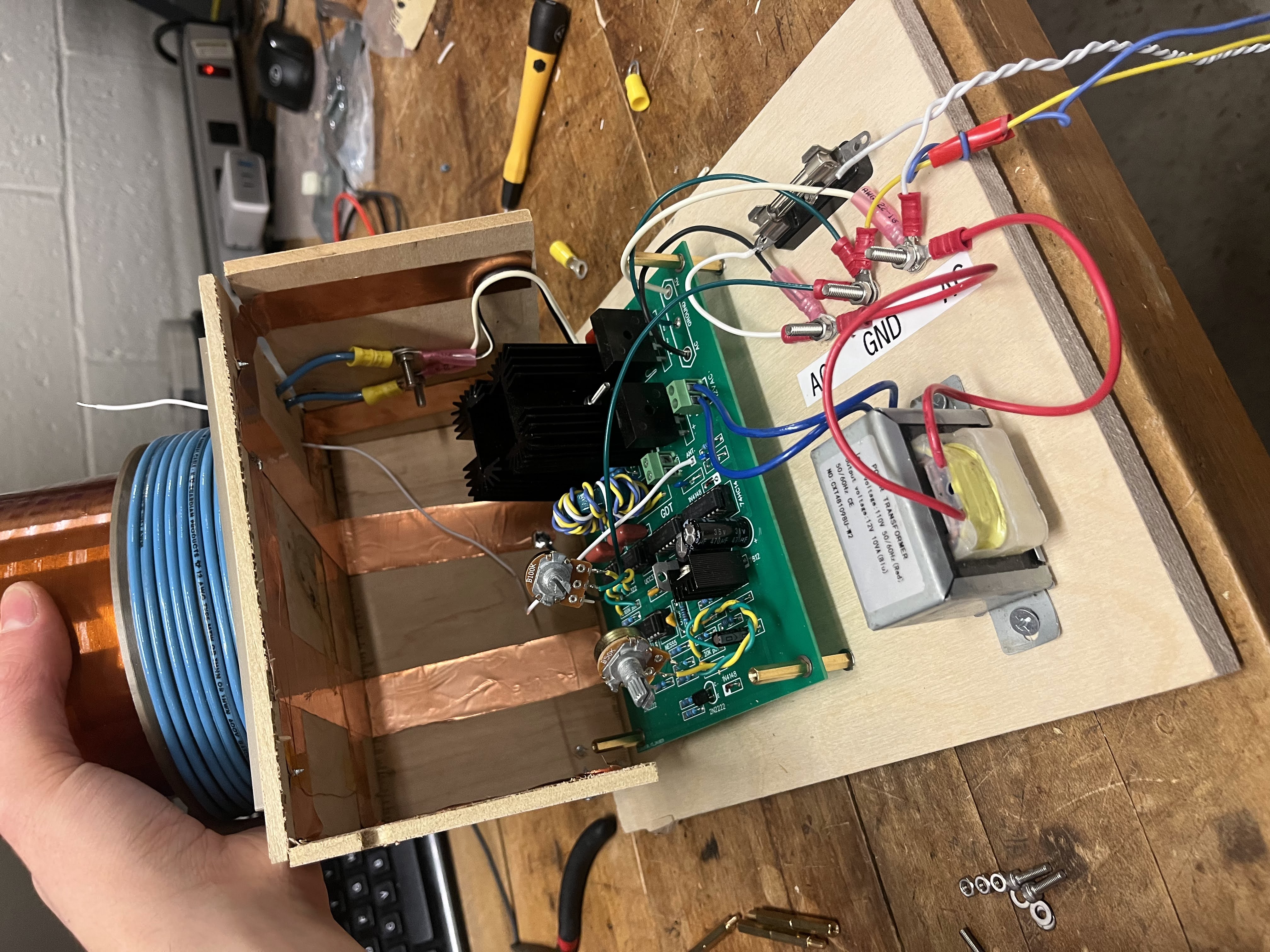
Here is the printed and populated circuit board in the wooden enclosure I built.^^
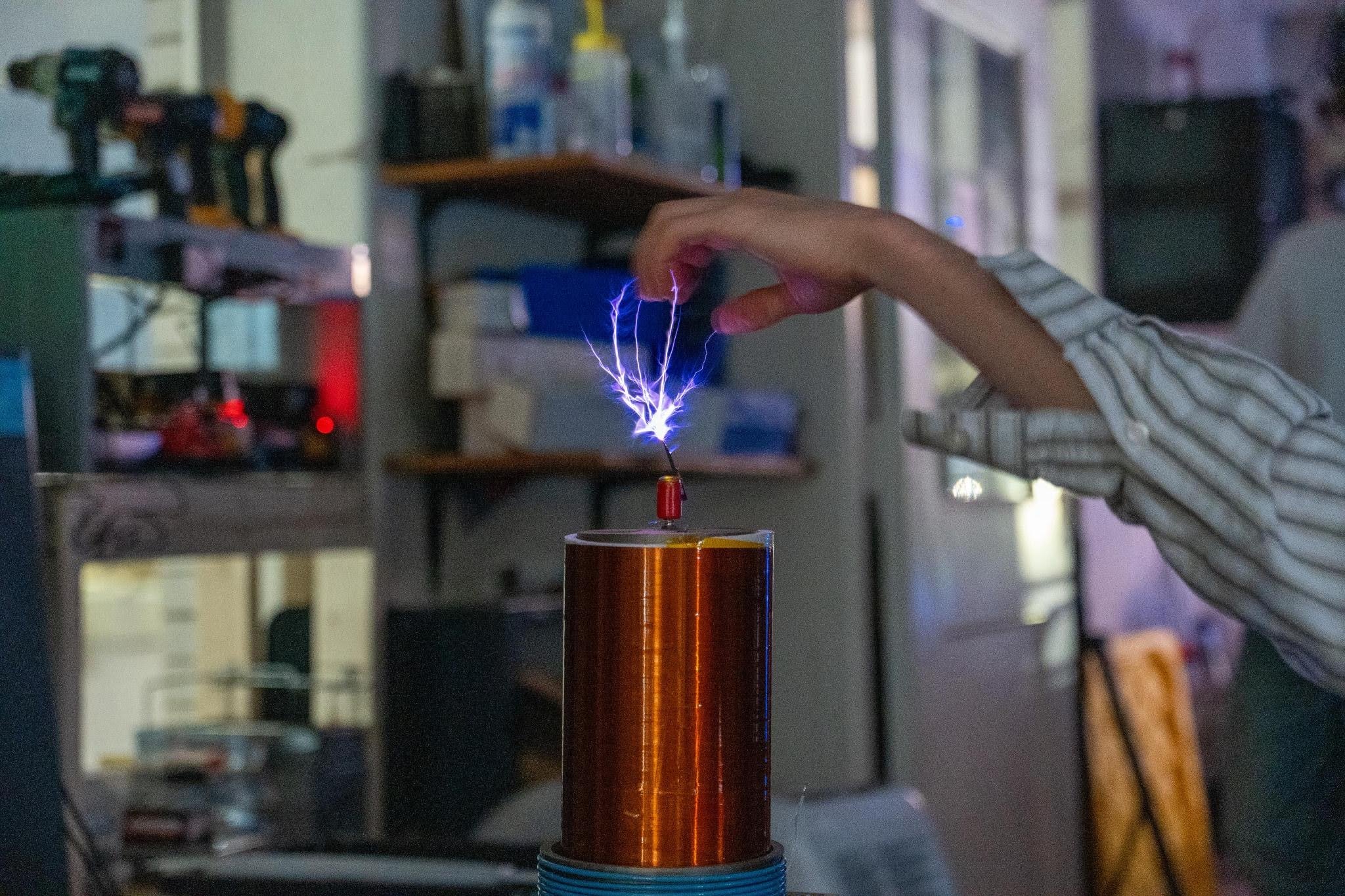
Glorious photo of arc curving toward my hand, courtesy of Tyler and his niiice camera!
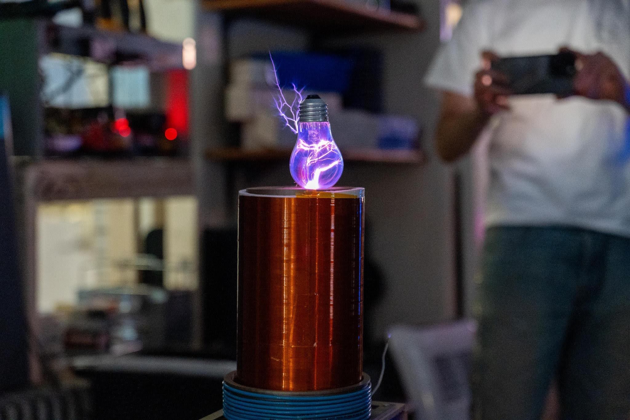
Here the coil is lighting the plasma in a normal tungsten light bulb.
Driver-less Solid State Tesla Coil!
I would regard this tesla coil as a proper Solid State Tesla Coil (SSTC). It switches the primary
off a large power mosfet which again, uses feedback from a direct electrical connection to the base of
the secondary.
This circuit runs right off of wall power at 120V input! The sparks coming out of this thing are
slightly lower frequency with a smaller coupling coefficient causing loooong sword streamers!
I've been getting ~6in streamers from this coil. I believe this circuit hits a few hundred kilovolts.
<----- This is a video of one of my first tests: using the coil to light a bulb and playing with the
tips of the sword arcs. You can't actually feel yourself getting electrocuted due to the high frequency
of the voltage. A lot of people talk about the dangers of internal burns and nerve damage, the latter
of which, I'm not sure about, but I do tend to conduct the arc through a screwdriver to prevent burns.
Here's a close up of the coil running at ~50% power. Huge arcs!
In this video, I run the coil at 36V, or ~25% power. You can see me excite plasma in a light bulb and conduct the arc through some tweezers.
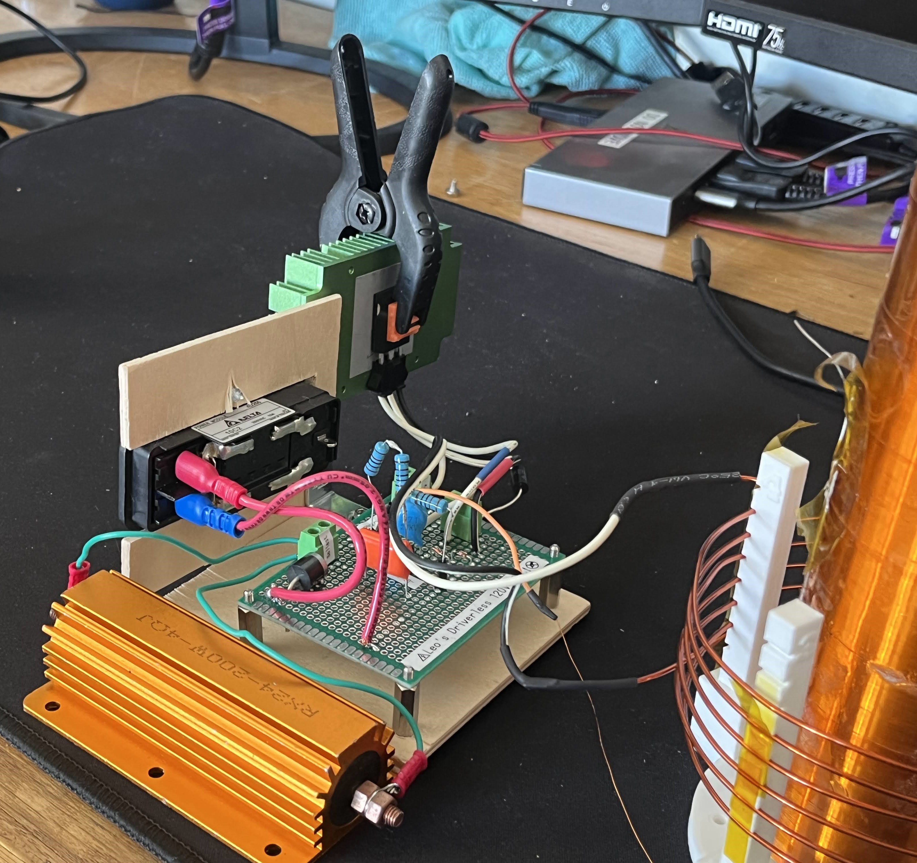
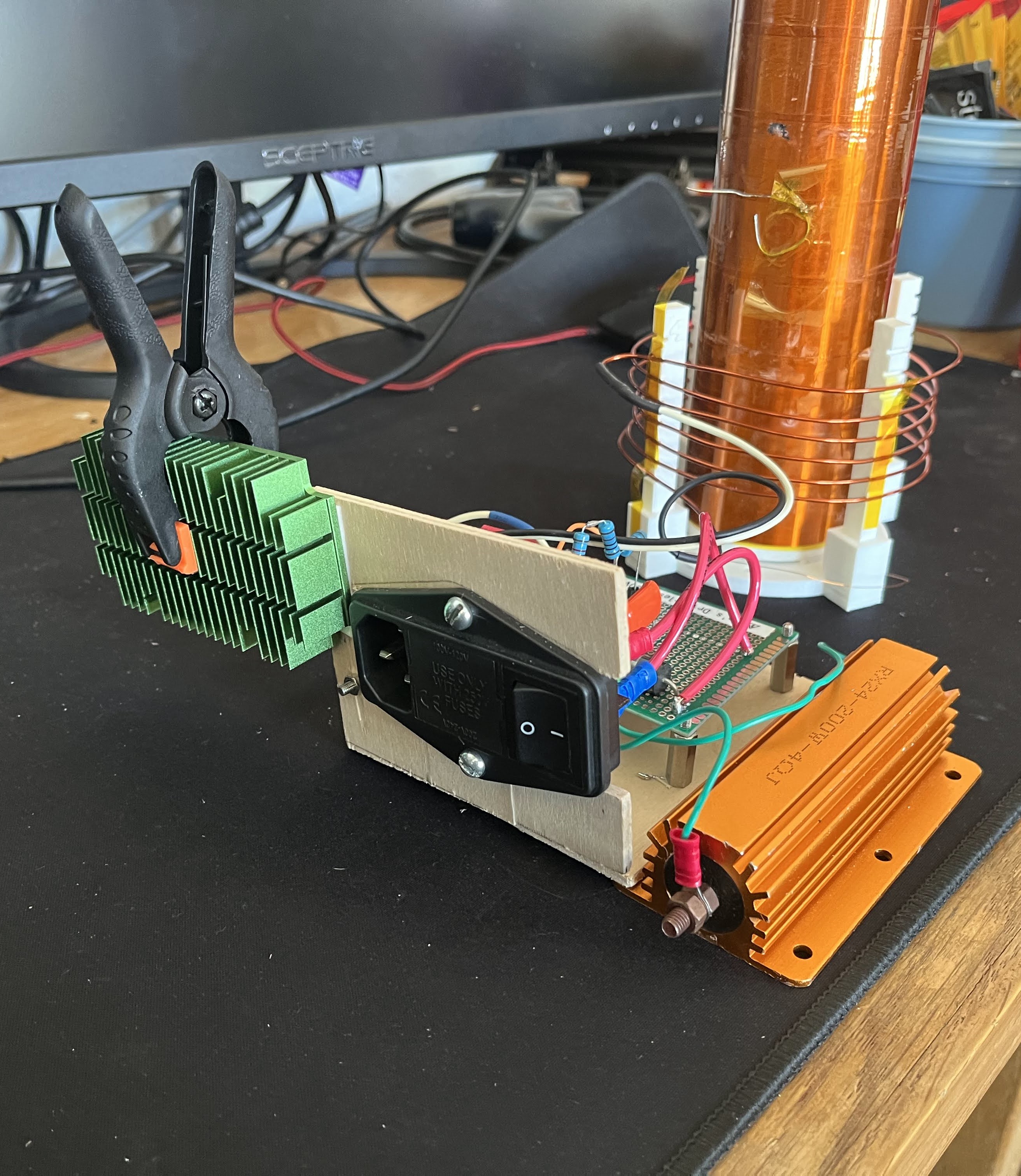
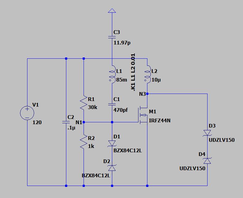
Here's the circuit driving the coil, it actually runs off an IRFP460 mosfet, which is rated for 200V and 20A. I bias the input to the threshold voltage with a resistor network and try to drain off spikes at the gate with a 12V TVS diode. Despite a direct electrical connection with the large primary inductance and high secondary voltage, the major protection for this mosfet comes from the 12V TVS diode from gate to source and the 200V TVS diode from drain to source. This circuit is more robust than the simple slayer exciter, but still easily breaks from a voltage spike into ground or overheating of the HV TVS diode. Note that the wiring schematic doesn't actually reflect my circuit, sorry.
Here's a full power test in wireless club. You'll notice that the arc forms at the center of the secondary, not at the top load. This is undesirable, I believe this is due to slow switching of the mosfet, which should have a dedicated gate driver circuit. Still many more things to fix!
At very low power, exciting plasma in a light bulb looks like a tiny jet of colored flame!