Electronics for quantum transduction and entanglement!
Updated 1/29/2025
This page showcases some electronics I made while working for the National Institute of Standards
and Technology during 2022(entanglement) and 2023(transduction). I focused largely on optics during
these periods but also made some neat devices!
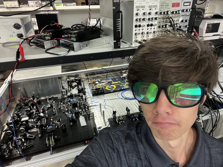
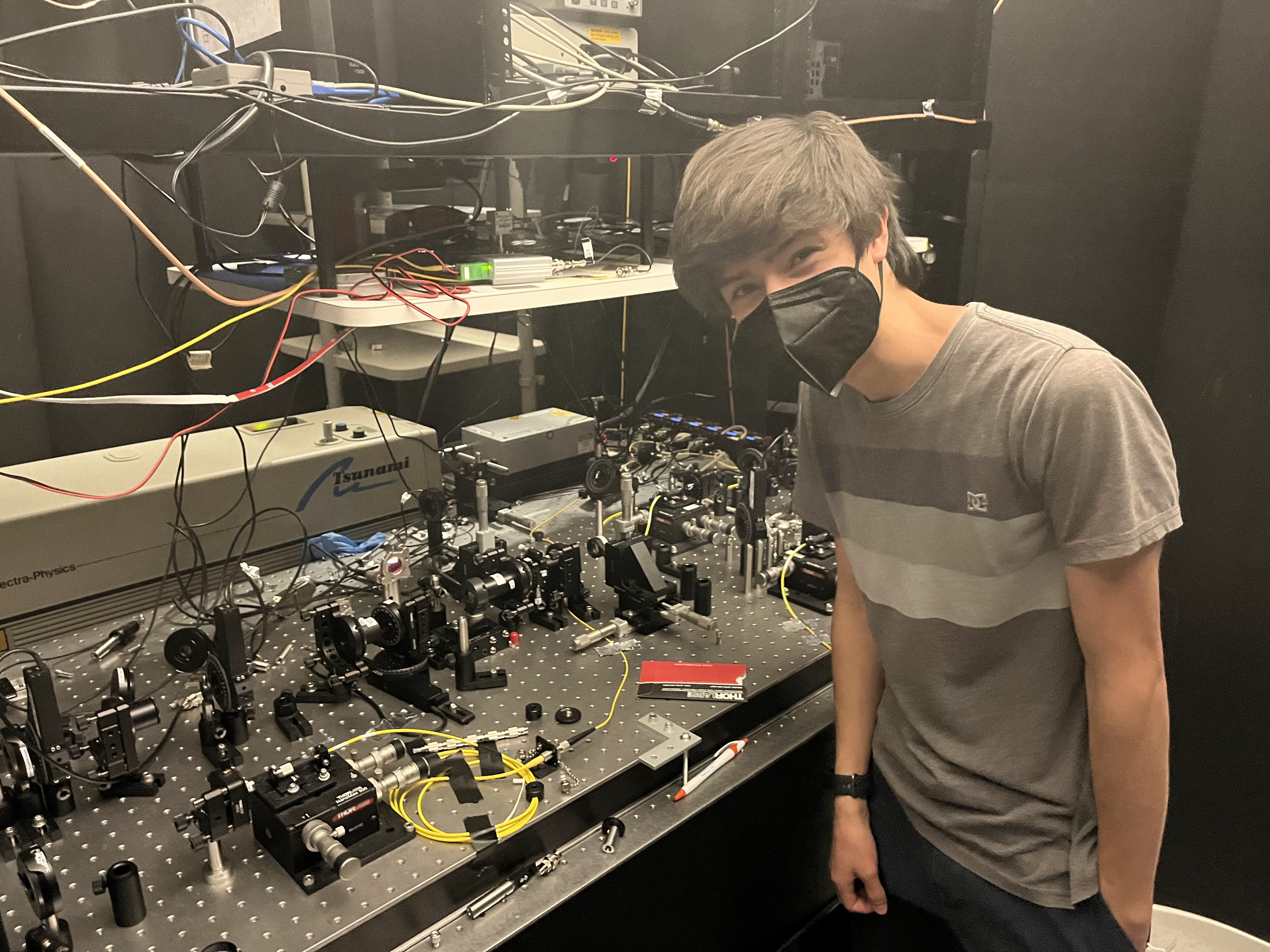
On the picture on the right I'm wearing a pair of 512nm reflective and 1024nm absorptive (those
are light wavelengths) glasses which cost $2000! Worth it to prevent being blinded by a
laser!
This pattern is from a camera and is actually what the "tip" of the laser beam looks like!
In 2023, I worked on a project focused on quantum transduction and optical networking of
superconducting quantum computers. Basically, quantum computers need to work at
millikelvin temperatures, so they're all in sealed refrigerators and can't send signals to other quantum
computers. Our project would transduce the microwave signal in the quantum computer to an optical
signal, which could leave the fridge and be sent to another quantum computer! Communication!
A large part of this experiment is conditioning the laser beam to be a super exact wavelength. This
involves bouncing the laser beam back and forth between two mirrors (optical cavity) and changing the
wavelength using an acousto-optic modulator, which is a crystal that can change the wavelength of light
passing through it based on an electrical signal you pass into it. I spent a lot of time setting up the
optical table for two of these "wavelength conditioners", one at room temperature and one with its optical
cavity in the cryogenic refrigerator. Aligning lasers is hard! I then built electronics to control the
acousto-optic modulator. My device drove the high frequency electrical signal being pumped into this crystal.
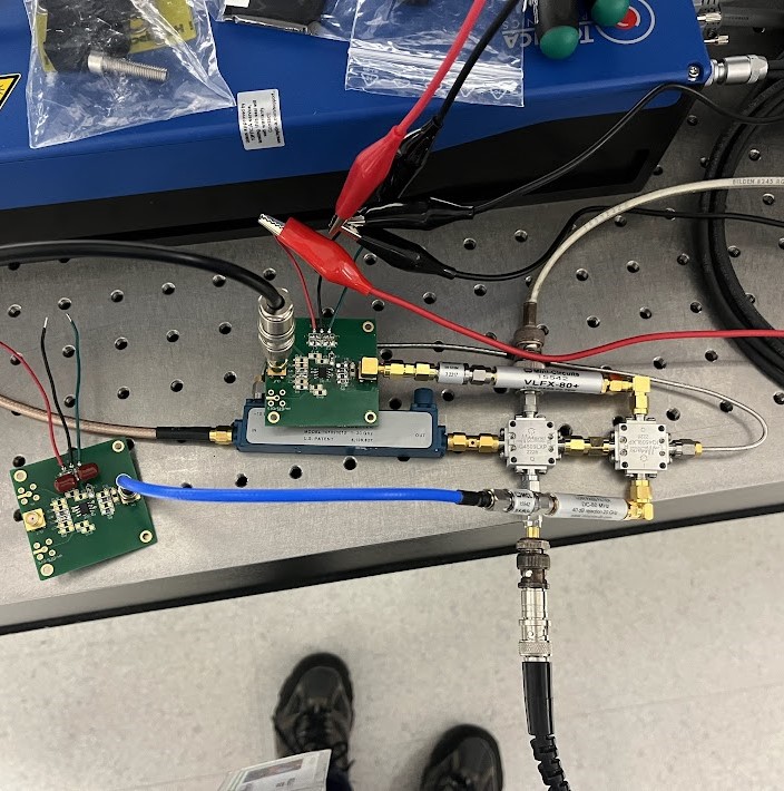
A small circuit I built off a schematic which uses two op-amps, some IQ mixers, and some filters and attenuators to band pass, attenuate, and mix high frequency signals to control a microwave laser circuit. I did not design these op-amp PCBs, but I did populate them with the correct SMD components for the circuit.
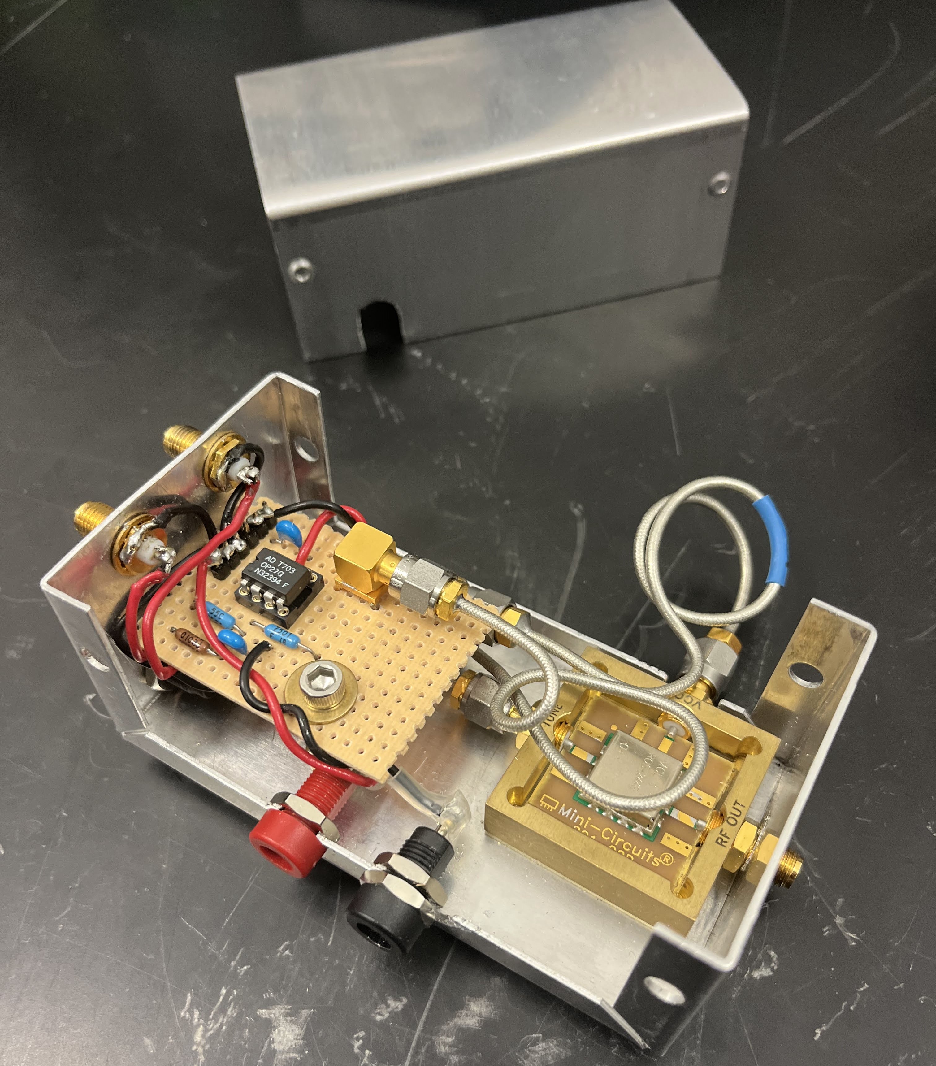
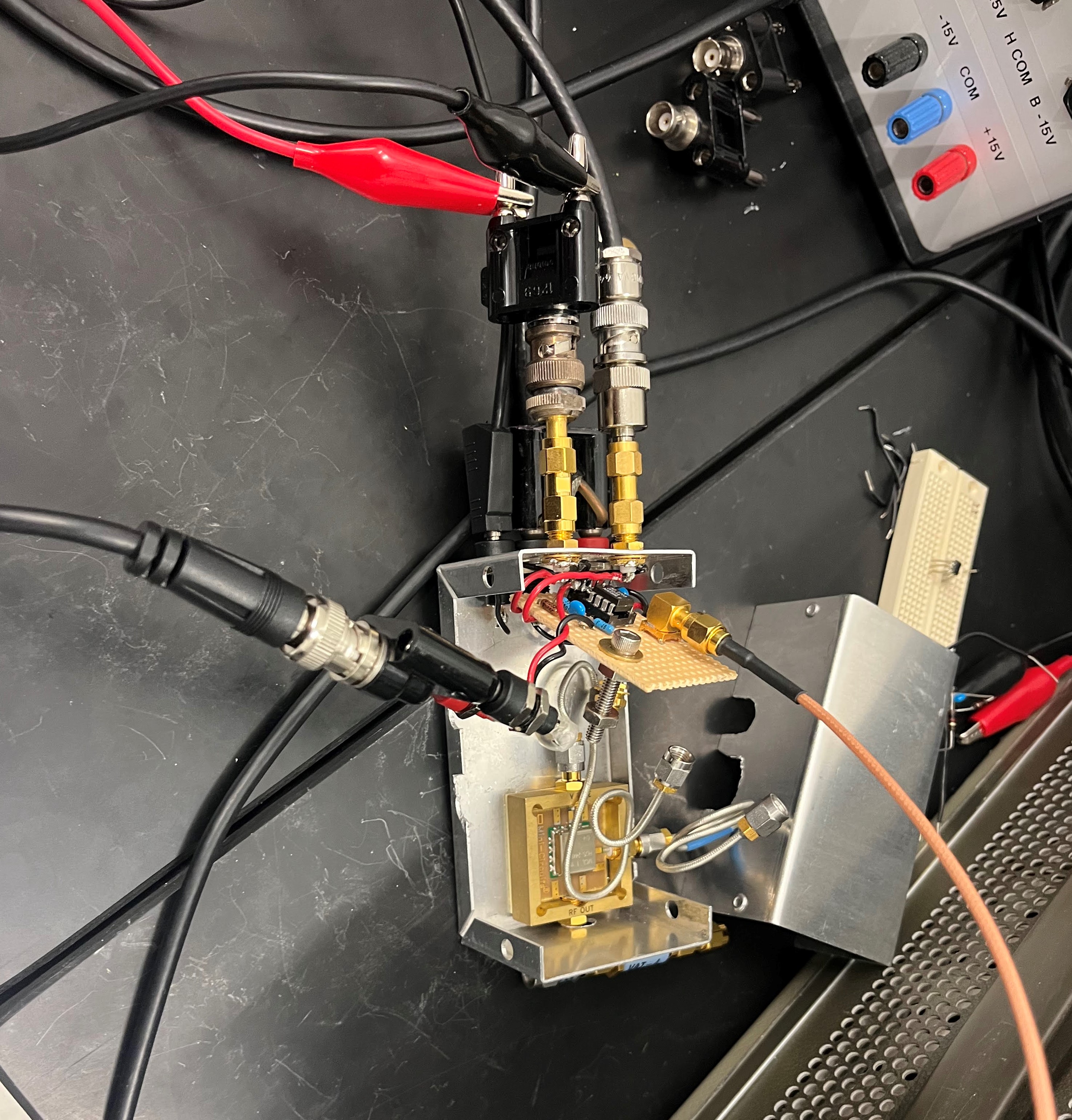
I fully designed and built this circuit, which adds two voltages, one with ~17db, and one with unity gain. It then generates a signal based off the sum using a voltage controlled oscillator(VCO). This signal varies in frequency based off the voltage, outputting an ~500MHz sine wave. This signal was used to drive an acousto-optic modulator, which lets you change a laser's wavelength.
Here's a short video of my electronics as implemented in the experimental setup.
That noise in the background is our pulse tube refrigerator keeping the experiment at
~6 degrees
kelvin!
I programmed a Red Pitaya FPGA as a proportional-integral-derivative controller to keep the laser
wavelength fixed with feedback. In this circuit, the input to the Red Pitaya is a laser power
meter, and the output is an analog voltage which is fed into my voltage-adder-VCO circuit. I also
programmed the Red Pitaya with custom python scripts to automatically read and save voltage drift data.
In 2022, I worked on NIST's Bell Test. An experiment to test quantum entanglement
principals. We were using it to generate super duper perfect random numbers. Our setup quantum entangled
individual photons based on their polarity and sent them to opposite sides of the lab to be measured for
quantum phenomena.
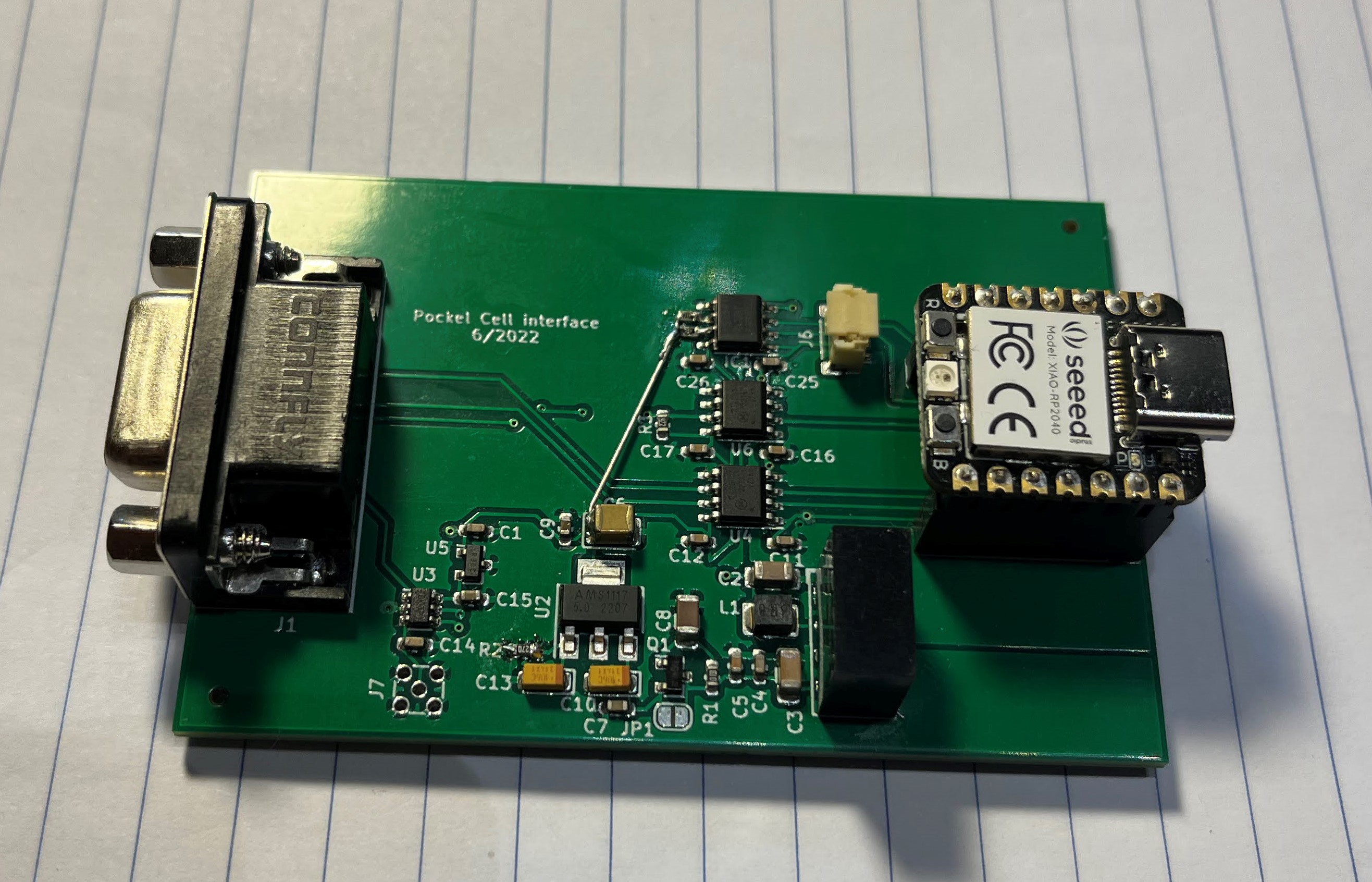
This circuit I helped to develop controls the remotely controls the driver for the high speed polarization switch
component called a Pockels Cell. My device allows a user to output a high-resolution analog voltage (among
other functions) to control the angle of photon polarization. Remote operation is achieved with a custom
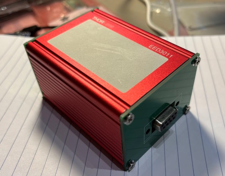
webserver and an ESP, meaning that the experiment can be operated completely remotely with my little box!
(Yes the sides of the box are made of custom PCBs)
This circuit creates a precisely filtered 5v DC voltage with a buck converter, transistor series voltage
regulator, and voltage regulator IC. This voltage is used as the voltage reference for the digital
to analog converter(DAC) IC. This system is controlled by a SEEED Xiao RP2040.
I wasn't very well
versed in analog circuits at this point, so I tackled the digital electronics. I was in charge of
the DAC, microcontroller, and output port of the circuit design. I programmed the microcontroller to
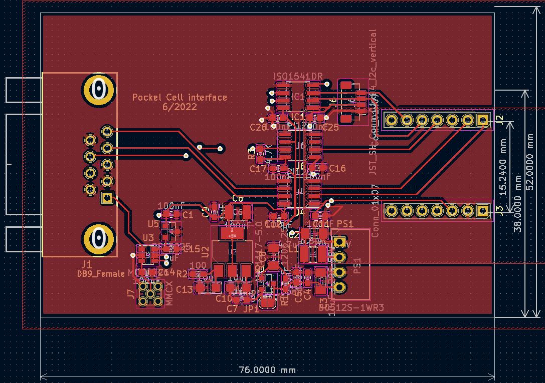
interface with a Raspberry PI running a web server for remote control. I was also in charge of laying
out the PCB to fit perfectly in one of our small aluminum cases! (bonus - I designed PCB covers for
the case haha)
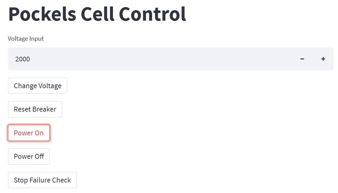
I programmed a custom GUI for my tool in python using a library called "streamlit". This device sucessfully remotely controlled the analog voltage and digital breaker, power, and failure IO pins to the high voltage driver equipment for the Pockels Cell. The user simply connects to the Raspberry Pi's webserver using a python script with Dockerfile to open the GUI in their browser, and control the device.
Me at the Bell Test entanglement generator / photon transmitter.